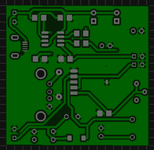
How to make a power bank ? Power bank Circuit Diagram. The article presents a handful of assorted power bank circuits using 1. V Li-ion cell which can be built by any individual for their personal emergency. The circuit uses two integrated modules and a lithium-ion battery.
The first module is a lithium-ion battery. With the help of this circuit diagram we can build our own power bank. If you are using simple volt battery you just follow the second picture of circuit diagram. Carefully check the finished circuit board before applying power , and try to mount the assembled circuit in a small plastic box, including the lithium-ion battery pack (better, rests on a double-sided glue-tape stuck on the bottom).
But here in this project, we are creating a single PCB instead. You need a 9V battery to use this power bank. This app is basically developed for assist. Dalian Jinseo Electronic Technology is leading supplier of high quality printed circuit board and related PCB services in China.
We specialize in manufacturing and. A typical power bank has these components: Charging circuit : it implements the complete charging logic for a Lithium Ion battery Battery Protection circuit : it takes care of over charge and over temperature protections. If the output voltage required would have been 3. However, power bank manufacturers prefer to use dedicated battery protection circuits outside the CPU. This is to ensure that the battery is always protecte even if the CPU has failed for some reason. This provides two levels of protection in power banks that use SoCs.
A power bank is a portable secondary battery that stores energy when alternating current (AC) power is not available. One port is mini USB, connecting the power bank to a USB charging adapter to store energy in the power bank. Good day sir, pls sir i have a power bank circuit here, it is not functiong well so when i yry testing the battery terminal on continuity mode, my multimeter beeps continuously, pls what could be the cause sir.
Find great deals on eBay for power bank circuit. Rechargeable power bank circuit. It is not called as short circuit but something else. Mobile power bank circuit board can be treated as a control system, which is mainly responsible for power distribution and transformation.
It converts the voltage provided by lithium batteries into the standard voltage to provide electricity for charging. Also let me mention this, lets say power bank is fully discharge when I try to charge it using (5v 850mA charger) power bank immediately shows LED even though it was fully discharged. This is a mechanism that ensures that the battery stops charging once it has reached full capacity. Tagged: cfl pcb circuit diagram, inverter pcb circuit diagram, mobile pcb. It can be used as a Portable Mobile Charger or it can be used for powering the bread board.

Request for Stock We will inform you when the product arrives in stock. No matter it’s branded power bank or generic power bank. But chances for both branded and generic power bank to explode are near to.
USB OTG cable (preferably a non-working one): Not needed if you are using a power bank case. Thin wires used for DC batteries (Red and Black): Not needed if you are using a power bank case. Kmashi’s MP8battery pack is a fairly average power bank with a standout price.
MP8significantly cheaper than other power banks with similar.
No comments:
Post a Comment
Note: Only a member of this blog may post a comment.