Great design of the 0-counter ! Instead of using a 5timer, I would like to use a momentary switch to trigger each pulse as a single event occurs. The best method of limiting the current through a seven segment display is to use a current limiting resistor in series with each of the seven LED’s as shown. A pulse divider (aka pulse counter ) produces an output pulse after a specific number of input pulses – in other words, it turns multiple input pulses into one output pulse. Because a pulse divider must count the input pulses to know when to produce an output pulse , it has some similarity to a ring counter (an n -state memory circuit with only one state on).
I am looking for a simple pulse counter circuit. A single monetary push button switch would act as the input. When eight pulses are received an. Although this is a fully functional circuit , it contains several interesting bits.
The input circuit consists of phototransistor Tfollowed by a high-speed switching transistor amplifier built around T2. It is important for students to consult the datasheet for the 74HCT1counter circuit in order to fully understand what is going on in these two cascaded counter circuits. Question A student wishes to cascade multiple four-bit synchronous counters together. The analog switch would then tie increasing size timing caps into the timing circuit.
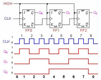
To see that this circuit operates as a binary counter a table can be prepared to show the Q output states after each clock pulse is applied. Table shows this operation for the circuit of Figure 1. A binary counter is a chip designed to count the number of pulses or events that occur in digital circuits. These chips memorize the events and show the count of events at output port. The chip memorizes the event and shows the output in binary code, hence the name BINARY COUNTER.
What binary counter does it each time a pulse is appeared at clock pin, it counts it and stores the value. Counter is a digital device and the output of the counter includes a predefined state based on the clock pulse applications. The output of the counter can be used to. An asynchronous (ripple) counter is a single d-type flip-flop, with its J (data) input fed from its own inverted output. This circuit can store one bit, and hence can.

Circuit Design, Low Prices. Operating details of the digital. In short high pulse on this input increments the counter. By connecting an astable to the clock input of a fixed frequency, the counter outputs can be used as timed outputs.
This “low” signal commands the counter circuit to decrement with every clock pulse from the encoder. A megohm is a safe value for most tubes. There are two ways of counting pulses, and we’ve used both in the emonTx. The first is “Interrupt-driven”, where an input pin is configured to trigger a software interrupt. Information about pulse counter circuit diagram has been submitted by Maria Nieto and tagged in this category.
Sometimes, we might need to slightly modify the layout. Sample Pulse Generator - A counter that increments every clock edge. When the maximum is reached a sample pulse is generated and the count value resets to zero.
The sample pulse is used to sample the switch input. The legal status is an assumption and is not a legal conclusion. This waveform can be then measured using an MCU having a pulse counter.

Sensors based on Pulse Counting Theory There are various sensors available that employ different techniques to generate electrical pulses in accordance with the flow being measured.
No comments:
Post a Comment
Note: Only a member of this blog may post a comment.