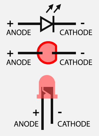
An electronics breadboard (as opposed to the type on which sandwiches are made) is actually referring to a solderless breadboard. These are great units for making temporary circuits and prototyping, and they require absolutely no soldering. Anyway i will only be using an led and some resistors to outline how a breadboard works. Note : a breadboard is a temporary circuit board for testing and prototyping circuits, no soldering is done on the boar this mean it is faster and easier to prototype circuits.
Our website uses cookies. By using our website, you consent to our use of cookies. Clicking Close will hide this popup for month. To find out more about cookies.
A solderless breadboard is a device used to quickly assemble temporary circuits by plugging wires and components into electrically common spring-clips arranged underneath rows of holes in a plastic board. A breadboard is a construction base for prototyping of electronics. Originally it was literally a bread board , a polished piece of wood used for slicing bread.

You will need a breadboard , an LED and a 1. K ohm resistor (brown black red gold). If you have a protoshiel make sure its assembled first. Then, place the tiny breadboard on top. Breadboard Electronics and more!
Include many basic components: breadboar resistors , LE rotary potentiometers, power supply module, button caps, jumper cables, etc. Free Delivery on Eligible Orders! Components in different types can meet varied demands of different experiment. For example, jumper wires and resistors work the same in both directions.
Look closely at these two images. Even though the jumper wire and resistor have been flipped. How to use variable resistors. The maximum resistance that a preset can provide is written on it.
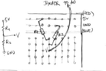
If 100K is written on preset, it means that we can. On breadboard there are horizontal lines in which points are there which are shorted. This lines are there at top and bottom of bread board if you keep it in palm. Below is a schematic diagram showing a closeup of the top section of the breadboard.
Start by plugging the resistors into the correct holes in the breadboard as shown. They should be cut to length so that they sit flat against the board when plugged in. This stops them wobbling about and avoids having long legs shorting out against other wires. The resistors can be plugged in either way aroun but it makes it easier to check the colour codes if they are inserted the same way.
Find great deals on eBay for breadboard components kit. Using resistors properly on a breadboard. This feature is not available right now. It’s got holes that are a good size for hookup wires and the ends of most components, so you can push wires and components in and pull them out without much trouble.

To connect a resistor in series, connect them end to end across one row so that the electrons MUST. The other lead of Rconnects to the top rail of the breadboard which will be where the positive lead of the battery connects. Insert the 22k Resistor (R2) Connect Rbetween the top rail and the negative terminal of C1.
No comments:
Post a Comment
Note: Only a member of this blog may post a comment.